Zorays Solar Pakistan
Look at an old farm windmill and then look at a modern electricity-generating wind turbine.
The difference is immediately obvious.
A traditional windmill may have a dozen or more blades packed around its rotor. A modern utility-scale wind turbine, despite being vastly larger and designed to generate enormous amounts of electricity, usually has only three.
At first glance, the old machine seems to have the better idea.
If blades capture energy from the wind, surely adding more blades should capture more energy.
Take that reasoning far enough and the perfect wind turbine ought to resemble a giant solid disc, leaving almost no empty space for the wind to pass through.
It doesn’t.
The reason reveals something fundamental about wind-turbine engineering:
The objective is not to put as much blade as possible in front of the wind. It is to make each blade interact with the moving air as effectively as possible.
And that distinction explains why three blades have become such a familiar feature of the modern energy landscape.
More Blades Once Made Perfect Sense
The multi-bladed windmills of the past were not badly designed versions of today’s turbines.
They were designed for a different job.
Traditional wind machines were commonly used for tasks such as pumping water and other mechanical applications. These machines benefited from producing relatively high torque at low rotational speeds.
Adding more blade area helped achieve that objective.
Modern electricity-generating turbines face a different engineering problem.
They need to convert the kinetic energy of moving air into useful rotational mechanical power and ultimately electricity, while controlling aerodynamic forces, structural loads, rotational speed, noise, weight and cost.
A rotor designed for electricity generation therefore does not necessarily benefit from filling its entire swept area with blades.
To understand why, we first need to distinguish the blade area from the much larger area through which those blades rotate.
A Wind Turbine Captures Energy Across a Circle
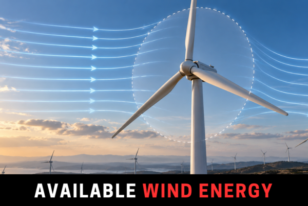
When a blade rotates, it sweeps through an area.
For a rotor with radius R:
A = πR2
This is called the swept area.
The available power in the wind passing through that area is:
Pwind = ½ρAv3
where:
ρ = air density
A = rotor swept area
v = wind velocity
Notice that this equation contains the area swept by the rotor.
It does not say:
Power = number of blades × some fixed amount of power per blade.
That distinction matters.
A blade repeatedly travels through the swept area and interacts aerodynamically with the moving air.
The engineering problem is therefore not simply how much physical material can be placed inside the rotor circle.
It is how effectively that rotor can extract useful mechanical power from the airflow.
Solidity: How Much of the Rotor Is Actually Blade?
There is a useful quantity in wind-turbine design called solidity.
In simplified terms, solidity describes how much of the rotor’s swept area is occupied by blades.
A traditional multi-bladed windmill has relatively high solidity.
A modern three-bladed turbine has much lower solidity.
At first, high solidity sounds desirable.
More blade surface means more opportunity to interact with the wind.
But it also changes how the rotor operates.
High-solidity machines tend to operate at relatively low rotational speeds while producing substantial torque.
Low-solidity rotors can operate much faster.
And for modern electricity generation, that difference becomes extremely important.
A Modern Turbine Blade Is Closer to an Aircraft Wing Than a Paddle
A common mental model of a wind turbine is that the wind simply pushes the blades around.
That is incomplete.
Modern turbine blades are aerodynamic structures.
Their cross-sections resemble airfoils, much like aircraft wings.
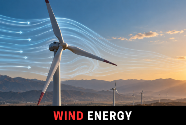
As air moves around an appropriately shaped blade, the airflow creates aerodynamic forces.
These can be resolved principally into:
Lift
and:
Drag
Lift acts approximately perpendicular to the relative airflow.
Drag acts approximately parallel to it.
Modern wind turbines are predominantly lift-driven machines.
The rotor geometry converts part of the aerodynamic lift force into torque around the turbine shaft.
That allows a relatively slender blade to interact very effectively with the airflow without requiring the rotor disc to be packed with material.
This is one of the central reasons comparing a modern turbine purely by its number of blades can be misleading.
The blades are not simply catching the wind.
They are aerodynamically extracting energy from it.
The Blade Can Travel Much Faster Than the Wind
Now we reach one of the most useful concepts in rotor engineering: the tip-speed ratio.
It is usually represented by the Greek letter lambda, λ:
λ = ωR / v
where:
ω = rotor angular velocity
R = rotor radius
v = wind velocity
The term ωR gives the tangential velocity of the blade tip.
So the tip-speed ratio essentially asks:
How fast is the blade tip moving compared with the incoming wind?
A tip-speed ratio of 1 would mean the blade tip is moving at approximately the wind speed.
A tip-speed ratio greater than 1 means the blade tip is travelling faster than the wind itself.
That can initially sound impossible.
But the wind is not simply pushing the blade downwind.
The aerodynamic forces acting on the airfoil-shaped blade produce rotation, allowing the blade tip to move through its circular path at a speed substantially greater than the incoming wind velocity.
This is characteristic of modern high-speed wind rotors.
Why Not Add Ten Blades to a High-Speed Rotor?
Imagine one blade passing through a region of air.
It changes that airflow.
Now place another blade immediately behind it.
Then another.
And another.
At some point, adding more blade surface stops producing proportional gains because each blade is increasingly interacting with airflow already influenced by the other blades.
There are also practical consequences.
Every additional blade adds:
mass,
material,
manufacturing cost,
hub complexity,
aerodynamic interaction,
and structural loading.
The question therefore becomes an optimization problem.
How much additional energy capture does another blade provide compared with what it costs and what additional loads it introduces?
Mukund R. Patel’s Wind and Solar Power Systems gives a particularly revealing example of this trade-off.
In the rotor designs discussed in the text, increasing the number of blades from two to three increases the power coefficient by only about 5%, while increasing blade weight and cost by roughly 50%.
That is diminishing return in an unusually visible engineering form.
More blade is not free.
And more blade does not produce proportional increases in power.
Then Why Not Use Only Two Blades?
This is where the story becomes more interesting.
If going from two blades to three provides a relatively modest aerodynamic improvement while adding another blade’s material and cost, why have three-bladed turbines become so dominant?
Because maximum aerodynamic power extraction is not the only design objective.
A commercial wind turbine has to survive enormous numbers of rotations over decades while dealing with changing wind speeds, turbulence, gravity, tower interaction and constantly varying mechanical loads.
Three blades offer several practical advantages.
They provide a more balanced rotor geometry.
The aerodynamic loading is distributed more evenly.
The machine generally has smoother rotational characteristics.
And the visual and acoustic behaviour of three-bladed machines has also proved acceptable for large-scale deployment.
Two-bladed turbines can and do exist.
But the engineering optimum for a commercial machine is determined by the whole turbine, not merely by which rotor produces the highest theoretical output for the lowest blade count.
That distinction appears repeatedly in engineering:
The best component in isolation is not necessarily part of the best system.
Why Not Four Blades?
Now apply the same reasoning in the other direction.
Going from two to three blades provides some aerodynamic and dynamic benefits.
Adding a fourth blade adds another substantial structural component.
Does it provide another equally substantial increase in energy capture?
No.
The gains continue diminishing.
Meanwhile, blade mass, hub requirements, loads and manufacturing costs continue accumulating.
At utility scale, this matters enormously.
A modern turbine blade is not a lightweight fan blade.
It is an enormous engineered composite structure exposed to millions of loading cycles.
Adding one is a serious economic and structural decision.
So the question is not:
“Would four blades capture slightly more aerodynamic power?”
It is:
“Would the additional lifetime energy and operating benefit justify the additional blade, structural requirements, loads, maintenance implications and cost?”
For most modern large horizontal-axis wind turbines, the industry answer has converged around three.
Blade Number and Rotor Speed Are Connected
Traditional windmills and modern turbines now start to make sense side by side.
A high-solidity rotor with many blades generally operates at a lower tip-speed ratio.
It can produce strong starting torque.
That can be useful for mechanical tasks.
A modern low-solidity rotor operates at a higher tip-speed ratio and uses carefully designed airfoils to generate useful torque while rotating considerably faster.
So when we see an old 15-bladed windmill beside a modern three-bladed turbine, we are not looking at an evolutionary progression from “inefficient” to “efficient” in a simplistic sense.
We are looking at machines optimized for different operating requirements.
One emphasizes torque at relatively low rotational speed.
The other is optimized as part of an electricity-generating system.
Why Aren’t Wind Turbine Blades Flat?
The same reasoning explains another obvious feature of modern turbines.
Their blades are not flat boards.
Their geometry changes along their length.
Near the hub, the blade is structurally substantial.
Moving outward, its shape changes.
The blade may also incorporate twist.
Why?
Because the entire blade does not move through the air at the same tangential speed.
Tangential velocity is:
vtip = ωR
A point close to the hub has a small radius.
A point near the tip has a much larger radius.
For the same angular velocity ω, the outer part therefore travels much faster.
The relative airflow experienced by the blade consequently changes along its length.
An intelligently designed turbine blade has to account for that.
What looks from the ground like a simple white blade is therefore an aerodynamic structure whose geometry reflects how different portions of the rotor interact with the air.
Why Are the Tips So Important?
Because the outer sections travel fastest, the blade tips are aerodynamically important.
They are also responsible for some difficult engineering problems.
Pressure differences around the blade contribute to tip vortices.
Higher tip velocities can increase aerodynamic noise.
Loads become significant.
And excessive rotor speed creates mechanical and control challenges.
This means engineers cannot simply maximize tip-speed ratio indefinitely.
Like blade number, tip-speed ratio has an optimum operating region.
The turbine has to balance energy extraction against aerodynamic, acoustic, structural and mechanical constraints.
This Is Where the Power Coefficient Returns
Not all power contained in the wind is captured by the rotor.
The fraction captured aerodynamically is described using the power coefficient, Cp:
Cp = Protor / Pwind
And Cp is not simply a fixed number stamped onto a turbine.
Rotor performance depends on operating conditions, including tip-speed ratio.
A useful way to think about this is:
For a particular rotor design, there is a rotational behaviour at which its blades interact especially effectively with the incoming wind.
Too slow and the rotor is not operating at its optimum aerodynamic condition.
Too fast and performance again deteriorates while loads and other constraints become important.
Modern turbine control systems therefore attempt to keep the rotor operating appropriately as wind conditions change.
The three blades we see from kilometres away are only the most visible part of a much more sophisticated aerodynamic and control system.
So Is Three the Perfect Number?
No universal law of physics says:
A wind turbine must have exactly three blades.
That is important.
Two-bladed turbines exist.
Single-bladed experimental concepts have existed.
Small turbines can use different rotor configurations.
Traditional machines use many blades.
Vertical-axis turbines can look completely different.
The three-bladed horizontal-axis turbine became dominant because it represents an extremely successful engineering compromise across numerous competing requirements.
Aerodynamic performance matters.
But so do:
weight,
cost,
structural balance,
fatigue,
rotational smoothness,
noise,
control,
manufacturability,
maintenance,
and lifetime energy production.
The optimum exists at the system level.
The Bigger Lesson Is About Engineering Optimization
There is an appealing simplicity to the question:
If blades capture wind, why not add more blades?
Because engineering rarely rewards maximizing one variable in isolation.
A bridge is not improved simply by adding more steel.
A battery system is not automatically improved by adding more capacity.
A solar installation is not necessarily better because more panels can physically fit on the roof.
And a wind turbine is not necessarily better because more blades can be attached to its hub.
Good engineering asks a different question:
What combination produces the best useful outcome under the real constraints of the system?
For modern utility-scale wind turbines, decades of aerodynamic, structural and economic optimization have made three blades an exceptionally effective answer.
Not because three is magical.
But because after a certain point, more stops meaning better.